Overclock Your Game Boy Advance SP
Game Boy April 3rd, 2007Here’s part 2 in our Game Boy Advance overclocking series. Do you want overclocked gaming action, but the screen on the original GBA is too dark because you never got your Afterburner kit? Why not overclock a GBA-SP?
What you need:
- Game Boy Advance SP
- GBAccelerator overclocking chip
- Tri-Wing Screwdriver
- Small Phillips screwdriver
- 30 AWG kynar wire-wrap wire
- Low-wattage, fine-tipped soldering iron
- Fine, rosin-core solder
- Wire cutters
- Wire stripper
- Needle-nose pliers
- Utility Knife
- Electrical tape
- Double-sided tape
- Cup or bowl to contain parts
Disassemble the SP
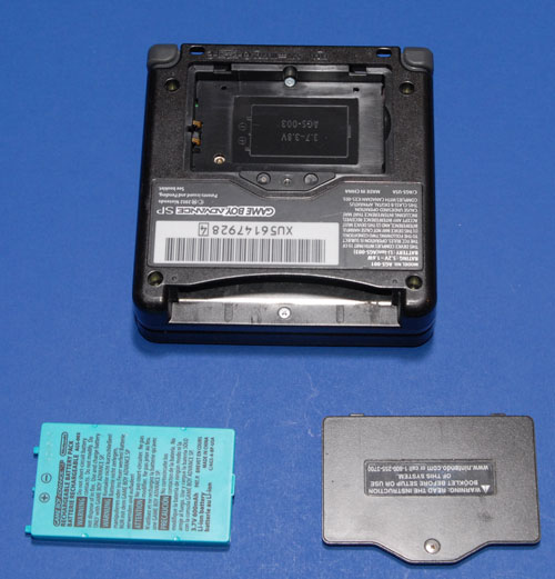
Turn the unit upside down. Use a phillips screwdriver to remove the battery cover. Pull the rechargeable battery out. Set the cover and battery aside.
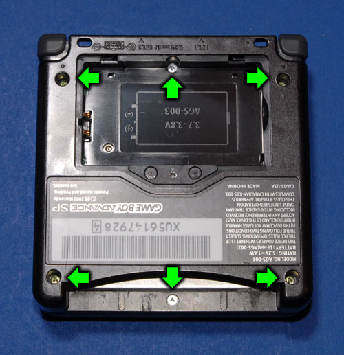
Use a tri-wing screwdriver to remove the remaining six screws from the back of the SP. Note: these screws are not captive like the one in the battery cover so you’ve got a pretty good chance of losing them. Put them in your hardware container!
Lift the cover off of the unit and set it aside.
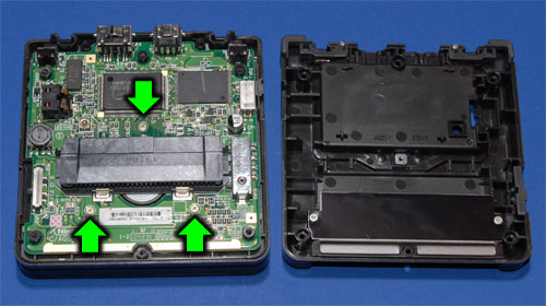
Remove the 3 screws that hold the PCB in place (tri-wing again). Carefully lift the board out of the case. It will still be attached to the LCD by a ribbon cable which will act like a hinge while you are lifting it.
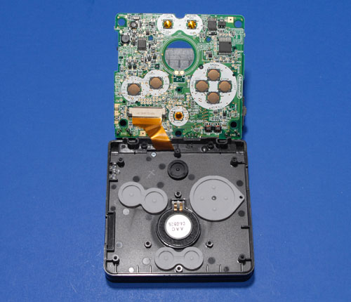
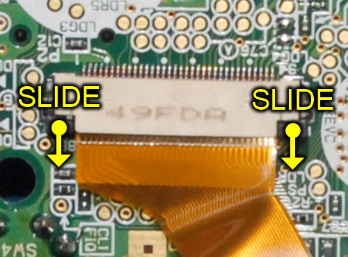
Detatch the LCD ribbon cable from the board by sliding the locking mechanism away from the connector with your fingernail. Set the top half of the SP aside, being careful not to lose any of the buttons, speaker or other hardware that is just sitting inside the case.
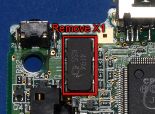
Remove Existing Crystal
Carefully desolder and remove crystal X1 from the back of the board. If desoldering it isn’t working, try the brute-force approach: Clamp down on it with a pair of needle-nose pliers and gently pull. Either it will pop off of the board or be crushed to bits by your pliers. Either way is no big deal since you’re replacing it with something better anyway. Be very careful when you are doing this that you don’t crack the PCB or damage any of the tiny SMT components right next to the crystal.
Install the GBAccelerator
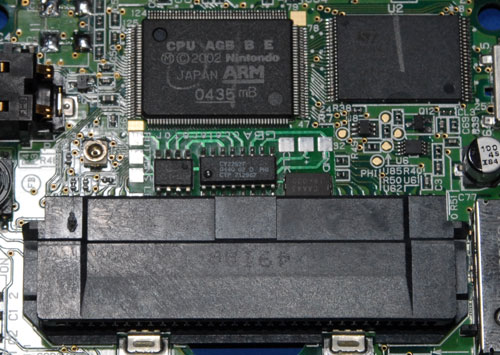
Cut a piece of double-sided tape that is a bit smaller than the GBAccelerator chip and stick it to the back. This will keep the chip from squirming around while you are trying to solder wires to it. Place the chip on the back of the SP board between the ARM CPU and the connector that the game cartridges connects to. Note: The LED solder pad on the GBAccelerator looks like it could easily short against one of the cartridge connector pins. You’ll probably want to put a piece of electrical tape between that pad and the connector.
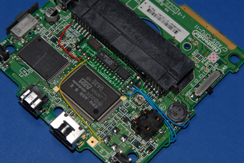
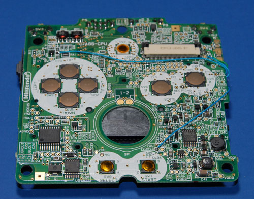
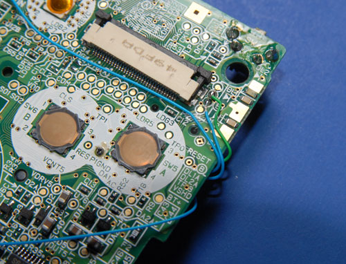
Start connecting wires according to the diagram. Try to route the wires like it shows so that they don’t pass over any screw holes or button pads. Note that four of the wires get wrapped around the edge of the board and get connected on the front. The three button inputs on the GBAccelerator chip are identical so it doesn’t matter which one you connect to which of the three listed solder points.
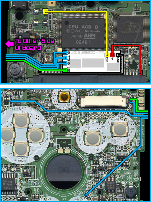
Here’s a list of connection points in case the diagram is hard to read:
|
GBAccelerator Connections
|
|
| GND | Cartridge Connector Pin 32 |
| V+ | Cartridge Connector Pin 1 |
| CLK | CK1 (solder pad where xtal used to be) |
| LED | DL2A |
| BUTTON | TP2 |
| BUTTON | TP8 |
| BUTTON | TP9 |
Don’t hold your soldering iron in one spot too long or the solder pads could overheat and lift right off! When you are all done soldering your installation should like a little something like this:
Reassemble the GBA-SP
Let’s start putting things back together. Reconnect the LCD ribbon cable to the connector on the PCB. Make sure it goes in as far as it will go and that the locking mechanism is slid back in all the way.
Set the SP board back in the top of the case and replace the screws that hold it in. Yes I know that one of the three holes is now covered up by the GBAccelerator chip. You didn’t really need all those screws anyway, so just leave that one out.
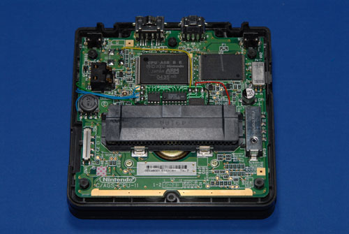
Use a utility knife to cut the two standoffs from the SP’s back cover as indicated. If you don’t, they will sit right on top of the new wires and keep you from putting the cover back on very easily.
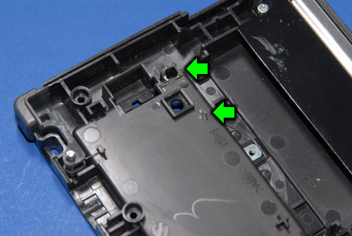
Put the back cover on the SP and reinstall the screws.
Install the battery.
Install the battery cover.
Insert your favorite game.
Turn the SP over.
Open the SP.
Try It Out
Now it’s time to test your handiwork! Turn the Game Boy on. It should start up and run just like it always did. Press L, R and Select simultaneously then release them. The game’s sound and video should be running faster now. You should also notice that the power LED now flashes red every once and a while. Press the 3 buttons again and the Powerpuff Girls should start flying even faster now (and the LED will double-blink). Want to take things down a notch? Press the buttons again for slow-motion mode (LED fades between green and red). One more press of the buttons will take you back to normal speed (LED steady green).


October 17th, 2013 at 2:28 PM
i should post a link to this page, from mine, if you dont mind, please reply, thank you
October 20th, 2013 at 1:29 PM
Wow great tutorial, ordered the GBAccelerator, followed your steps, BANG… Brand new and improved gba sp. Great for playing Pokemon Fire Red on my Supercard and EZ Flash! Thanks!
October 20th, 2013 at 1:46 PM
Cool, glad it was helpful!
December 20th, 2013 at 12:31 AM
Hi! Someone in my Myspace group shared this website with us so I came to check it out.
I’m definitely enjoying the information. I’m bookmarking and will be
tweeting this to my followers! Outstanding blog and excellent style and design.