Gain Structure
Audio April 30th, 2008What is gain structure? It’s the thing that can make thousands of dollars worth of sound gear sound really bad if you do it wrong. Even when your sound system is turned down to the point where it is very quiet it can still sound distorted if it is clipping anywhere along the signal path.
Gain
Gain, in the audio sense of the word, is the amount a signal is boosted or cut. If a particular device has a gain of 0dB then the signal leaving it will be at the same level as when it entered. If it has a gain of +5dB then the outputted signal is 5dB higher than the inputted one. If the gain is -5dB then the signal is actually cut by 5dB.
Each device in a signal path has a certain amount of gain, and a single device (like a mixer) can even have several sections, each with its own gain. As the signal goes from its source to one device and then the next and the next it gets boosted and cut along the way, depending on the settings of each device. This combination of various gains is called “gain structure”.
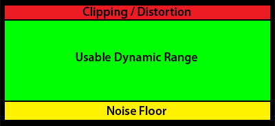
It’s natural to think that you can use any combination of gains you want along the signal path as long as the signal that comes out at the end is at the level you want. The problem with this is that all audio devices have a certain range of levels they work best with. If the signal is too low it can get below the noise floor. If it is too high it will suffer from distortion.
Noise
All electronics introduce a small amount of noise into a signal passing through them due to the random movement of electrons. If a signal is at or below the noise floor (level of noise in a system) then it will get lost in that noise. Ideally you want your signal to be as far above the level of the noise as possible so that when it is being played at the desired volume the noise is very quiet or completely inaudible. Of course there is a limit to how high your signal can be too, otherwise it will become distorted.
Distortion
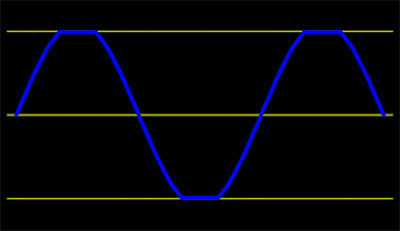
At some point the electronics in your audio device reach the maximum voltage which they will reproduce accurately. Since an audio signal is an AC wave the peaks of the waveforms start getting squished (clipped) resulting in the output wave not being a louder copy of the input wave but something slightly different (distorted). The higher you crank the signal the more it has to squish the wave and the worse it sounds.
Note: Analog equipment tends to clip a signal gradually as it starts getting to loud, but once digital gear reaches its maximum there is no more headroom. Digital clipping sounds very harsh and you should try very hard to avoid it.
Setting Up Gain Structure
The idea here is to have your audio signal survive the trek through all your audio gear without distorting or being lost in the noise.
Let’s say you are setting up a simple playback system for a museum display that consists of a CD player, a mixer, an amplifier and a speaker. Hook everything up, turn all the levels down on everything and turn it on. Start playing the CD. Now work your way through the system from source to output, adjusting gains as you go.

The CD player probably doesn’t have anything that can be adjusted. This is fine since it would be manufactured so that no matter how hot the signal on the CD is the signal coming out the output will not be distorted (unless the CD recording itself is). The audio on the CD you are using is probably well above the noise floor of the player so no worries there either.

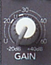
Now on to the mixer. Most mixers have two gain settings for each channel plus a master level that all need to be adjusted. We’ll start by adjusting the gain or pad control for the channel that the CD player is hooked to.
Your mixer should have a button on the CD channel marked PFL (Pre-Fader Listen) or Solo. Pushing this button taps into the signal after it comes into the mixer but before it gets to the channel fader and sends it to the meter (and also the headphone output).
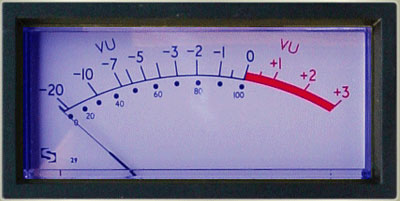
Adjust the gain so that the meter peaks at say +7dBu or so. This will make sure the signal is well above the noise floor but will give it some headroom for peaks that the meter may not be fast enough to display.

Note: This is the part of the signal path where the “sound is really quiet but is still distorted” problem mentioned at the beginning of the article usually occurs. The signal is fed into the mixer way to hot, it distorts, then it is turned down again by the channel fader.
Okay, now release the PFL / Solo button so the meter goes back to displaying the output level.
Set the channel fader to 0dB or U (Unity Gain) or however it is labeled on your mixer.
![]()
Now set the master fader at 0dB / Unity.
What you’ve done is set the level of the signal properly as soon as it enters the mixer, then made sure it stays the same the rest of the way through it. Now on to the amplifier.
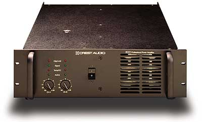
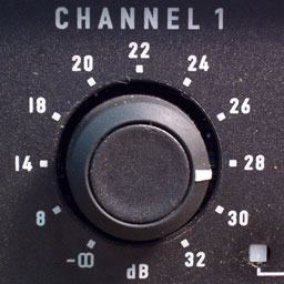
Adjust the level controls on the amplifier so that the sound coming out of the speaker is at the desired volume.
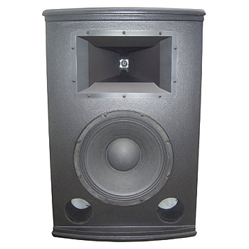
You should now hear some nice, crisp clean audio coming out of that speaker. If it is clear at lower volumes but becomes distorted as you approach the desired level then you probably need a more powerful amplifier or a higher-rated speaker.
Well, now you know the basics of gain structure. There’s plenty more to learn about the subject but if you’re just setting up a basic sound system you should be ready to go.

